Current transformers work quietly behind switchgear doors, yet their readings can shape protection decisions, equipment ratings, and maintenance actions. A small insulation defect or incorrect accuracy class can matter when fault current rises. That is why asking “What safety standards must current transformers comply with” is more than a paperwork exercise. It is a practical question about predictable performance under electrical and environmental stress.
IEC 61869-2 covers requirements for inductive current transformers and is used alongside the broader IEC 61869 series. In North America, IEEE C57.13 provides requirements for instrument transformers, while applicable product and installation rules may add further obligations. The exact standards depend on the market, application, voltage level, and whether the transformer is used for measurement or protection. Check the current editions and local requirements. Standards change, and an old specification can leave gaps.
A useful engineering principle is simple: “A current transformer is safe only when its ratings, installation, and intended use agree.” That is an editorial summary, not a verified quotation from a named expert. I would not attach it to an individual without a reliable source. In practice, engineers review insulation levels, thermal and dynamic ratings, secondary-circuit grounding, and burden limits. They also confirm that test reports match the exact model supplied. A label alone is not enough. Compliance reduces avoidable risk, but it cannot replace sound installation, inspection, and clear operating procedures.
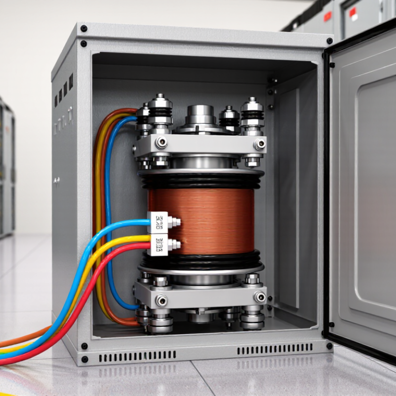
A current transformer (CT) measures electrical current by electromagnetic induction. Current in its primary conductor creates a magnetic field in the core. This field induces a smaller, proportional current in the secondary winding. For example, a 1000:5 CT produces 5 amperes on its secondary when the primary carries 1000 amperes, under its specified operating conditions. A meter can then read that reduced current safely. The circuit is easier to monitor.
Accuracy depends on the CT’s design, connected burden, and operating current. IEC 61869-2:2012 sets performance requirements for inductive current transformers. For Class 0.2S, its specified ratio-error limit is ±0.2% from 20% to 120% of rated current; at 1%, the limit is ±0.75%. These figures help engineers select a transformer for measurement tasks. They also show why readings can be less precise at very low loads.
Installation details matter just as much. An energized CT’s secondary must not be left open, because dangerous voltage can develop across its terminals. Keep the secondary circuit connected to its meter or use an approved shorting link during maintenance. Check the nameplate ratio and burden before commissioning. One detail is easy to overlook: a correctly sized CT can still give poor readings if its wiring is loose or its load exceeds specification. Safety rules are practical safeguards, not paperwork.
A noncompliant current transformer can create hazards that are difficult to spot during routine operation. Its insulation may not withstand the voltage or contamination present in a real installation. A cracked housing or loose terminal can expose energized parts. The danger can increase in a damp switch room or near vibrating equipment.
An open secondary circuit is especially hazardous when the primary conductor is energized. Dangerous voltage may appear across the secondary terminals, risking electric shock, burns, or insulation failure. That risk is easy to underestimate. Incorrect ratio or accuracy can also mislead meters and protection relays. A relay that reads too low may not trip when equipment overheats or a fault occurs. The result can be damaged cables, switchgear, or nearby equipment.
Ratings matter. The transformer must suit the system’s voltage, current, burden, and expected fault conditions. Poorly matched equipment can overheat, distort readings, or fail under stress. During commissioning, qualified personnel should check wiring, polarity, burden, and protective connections against the device documentation. Inspection matters too: look for cracked insulation, corrosion, loose connections, and signs of heat. Paperwork alone is not enough, though it is sometimes treated that way. A careful installation and periodic review reduce risks, but they cannot make an unsuitable transformer safe.
| Safety or performance area | Relevant requirement or principle | Good engineering practice | Hazard of a noncompliant or unsuitable CT |
|---|---|---|---|
| Applicable standards | IEC 61869-1 sets general requirements for instrument transformers; IEC 61869-2 adds requirements for inductive current transformers. IEEE C57.13 is another instrument-transformer standard used in applicable markets. | Select the standard required by the project, jurisdiction, and equipment specification, and verify the CT’s documentation and ratings against it. | Unverified construction or ratings can lead to unsafe installation, failed testing, or unreliable measurements and protection. |
| Open-circuit secondary | An energized CT secondary must not be left open. With primary current flowing, a high secondary voltage may develop. | Short the secondary using an appropriate shorting terminal block before disconnecting instruments or relays. Follow the CT and installation instructions. | Electric shock, arcing, insulation damage, and hazardous voltage at secondary terminals. |
| Accuracy and burden | CT accuracy depends on its specified accuracy class and operating conditions, including secondary burden and current range. IEC classes include measuring classes such as 0.2 and 0.5, and protection classes such as 5P and 10P. | Choose a class and rated burden suitable for the connected meter, relay, leads, and intended operating range. | Measurement error can affect billing, monitoring, or energy management; unsuitable protection performance can delay or prevent relay operation. |
| Protection performance and saturation | Protection CTs must be selected for the system fault-current and relay requirements. Core saturation can distort the secondary current during high-current events. | Check the CT’s protection class and relevant performance data against fault levels, relay burden, and the protection study. | Distorted current signals may cause delayed, incorrect, or failed protective tripping, increasing equipment-damage and personnel risks. |
| Insulation and voltage rating | Insulation level and rated voltage must be appropriate for the equipment and installation environment, as specified by the applicable standard and product documentation. | Confirm rated voltage, insulation level, clearances, and installation conditions before commissioning. | Insulation breakdown can result in electric shock, short circuits, fire, or damage to connected switchgear. |
| Polarity and terminal identification | CT polarity and terminal markings are important for correct measurement, power direction, and differential or directional protection schemes. | Check terminal markings against the wiring diagram and verify polarity during installation and testing. | Incorrect connections can produce misleading readings or impair protection functions. |
| Thermal and mechanical ratings | Rated continuous current and short-time thermal and dynamic withstand capabilities must suit the expected service and fault conditions. | Compare nameplate ratings with normal current, prospective fault current, and the specified fault-clearing duration. | Excessive heating or electromechanical forces can damage the CT, insulation, conductors, or adjacent equipment. |
| Testing and traceability | Routine and type-test requirements are defined by the applicable standard and product specification; records help confirm the unit’s declared performance. | Review test certificates and nameplate data, and perform installation checks and commissioning tests appropriate to the project. | Undetected defects or incorrect specifications may remain in service and create operational or safety failures. |
Note: Applicable requirements depend on the jurisdiction, system design, and project specification. Installation, testing, and maintenance should be performed by qualified personnel using the manufacturer’s instructions and site safety procedures.
Current transformers may look like simple rings around a conductor, but their design affects both measurement and worker safety. Applicable standards specify insulation levels, temperature limits, mechanical strength, and performance under expected electrical loads. They also help ensure the secondary circuit is correctly rated for its connected instruments. A design that ignores burden or fault conditions can overheat or produce unreliable readings. Small details matter.
Tips: Check nameplates, wiring diagrams, and terminal markings before work begins. Keep the secondary circuit properly connected or shorted when required by approved procedures. Never assume two similar-looking units share the same ratings.
Testing and installation should follow the standards and procedures applicable to the site and equipment. Qualified personnel can verify insulation, polarity, ratio, and grounding with suitable test instruments. During installation, secure the transformer, maintain required clearances, and inspect connections for looseness or damage. Record test results and any deviations for future maintenance. In practice, a rushed label check is easy to dismiss; it should not be. Even a careful process can miss something, so independent review is worth considering.
A current transformer may look like a simple ring around a cable, but it connects high-current equipment to meters and protective relays. If its secondary circuit is left open while energized, hazardous voltage can develop. This can injure a worker and damage insulation or connected equipment. The risk is easy to underestimate.
Applicable safety standards set requirements for insulation, temperature rise, mechanical strength, markings, and testing. Meeting them helps ensure a transformer is suitable for its voltage, current, and installation conditions. Clear terminal labels and correctly rated connections also reduce wiring mistakes during maintenance. Small errors matter. A loose connection can heat up; an incorrectly selected unit may give unreliable measurements when a fault occurs.
Compliance is not a magic shield. Even a tested transformer can be installed poorly, and that deserves honest attention. Technicians should follow the manufacturer’s instructions, verify connections, and use shorting provisions when servicing an energized circuit, where the design requires them. A careful inspection of terminals, cable routing, and enclosure condition can catch problems before they threaten people or equipment.
How compliance protects people and equipment
This chart shows the ideal current relationship for a 100:5 A current transformer: a 20:1 ratio, so 100 A primary corresponds to 5 A secondary. Actual performance depends on the transformer and its operating conditions. Follow applicable standards and manufacturer instructions for installation and insulation, and never open-circuit an energized CT secondary, as it can develop hazardous voltage.
Responsibilities of Manufacturers, Installers, and Operators
Manufacturers must design current transformers (CTs) for their stated voltage, accuracy class, burden, and thermal limits. IEC 61869-2:2012 sets additional requirements for inductive current transformers; IEEE C57.13 also specifies instrument-transformer requirements. Clear nameplates and test records help installers select suitable equipment. Small labeling gaps can create real confusion later.
Installers should verify the ratio, polarity, insulation condition, and secondary wiring before energizing a CT. Secure terminals matter. An energized CT secondary must not be left open: dangerous voltage can develop. Operators should keep shorting links accessible, check connections during maintenance, and record unusual heat, noise, or damage.
The risk is not theoretical: the U.S. Bureau of Labor Statistics recorded 145 fatal work injuries involving exposure to electricity in 2022. That figure covers many electrical hazards, not CT incidents alone, but it underlines why disciplined procedures matter.
Tips: Before testing, confirm the secondary circuit is safely shorted where required. Compare readings with commissioning records. If a label, connection, or result seems unclear, pause and ask a qualified specialist. Checklists help, but they cannot replace sound judgment.
Current in the primary conductor creates a magnetic field. The core transfers that field to a secondary winding, producing a smaller proportional current. A meter reads this reduced current.
When the primary carries 1000 amperes, the secondary produces 5 amperes under specified conditions. The exact reading depends on the transformer’s operating limits.
Design, connected burden, and operating current all matter. Readings may be less precise at very low loads. Small wiring issues can also distort results.
An open secondary can develop dangerous voltage across its terminals. Keep it connected to its meter, or use an approved shorting link during maintenance. Never guess.
Check the nameplate ratio, burden, terminal markings, and wiring diagram. Similar-looking units may have different ratings, so appearance alone is not enough.
Qualified personnel can verify insulation, polarity, ratio, and grounding with suitable test instruments. Record results and note any deviations for future maintenance.
Secure it, maintain required clearances, and inspect connections for looseness or damage. A loose wire can spoil readings, even with a correctly sized unit.
Applicable standards address insulation, temperature limits, mechanical strength, and performance. A second review may catch a missed detail; even careful checks are not perfect.
Current transformers measure electrical current by converting high current into a smaller, proportional signal that instruments and protective systems can safely use. Because they operate within electrical installations, their design, testing, and installation must address insulation strength, temperature limits, mechanical durability, accuracy, and protection against foreseeable faults. What safety standards must current transformers comply with depends on their intended application, location, and the requirements set by relevant technical authorities.
Using a noncompliant transformer can lead to inaccurate readings, overheating, electric shock, equipment damage, or failures in protective systems. Compliance helps reduce these risks by establishing consistent requirements for construction, testing, labeling, and safe installation. Manufacturers are responsible for designing and documenting products appropriately; installers must select, connect, and mount them correctly; and operators should arrange inspections and maintenance. Together, these responsibilities help protect people, electrical equipment, and the reliable operation of the wider installation.

Smrtr Technology