Selecting a transformer for a GFCI-protected installation is not simply a matter of matching voltage and wattage. The protection level changes how leakage current, insulation, grounding, and load behavior must be evaluated. This article explains How to select transformers for different GFCI protection levels in 2026, using practical engineering considerations rather than assumptions. A workshop circuit, a hospital-grade application, and an outdoor pump may require very different transformer characteristics. The wrong choice can cause nuisance trips, excessive heat, or inadequate protection.
Real projects often reveal details that product sheets overlook. A transformer may meet its rated VA capacity, yet struggle with motor inrush or electronic loads. A shielded isolation transformer can reduce unwanted noise, but it does not replace proper GFCI protection. Designers should examine primary and secondary voltage, fault current, leakage current, grounding arrangements, enclosure ratings, temperature rise, and certification requirements. Physical conditions matter too. Dust, moisture, cable length, and crowded control panels can change performance. Small details matter.
Reliable selection also requires current manufacturer data and qualified review. Requirements can differ by region, equipment type, and installation environment. Verify applicable 2026 standards before approving a design. Some assumptions may fail. That is worth admitting. When uncertainty remains, measure the actual load, confirm trip thresholds, and consult a licensed electrical professional. A careful transformer choice improves safety, reduces unwanted interruptions, and supports dependable operation over time.
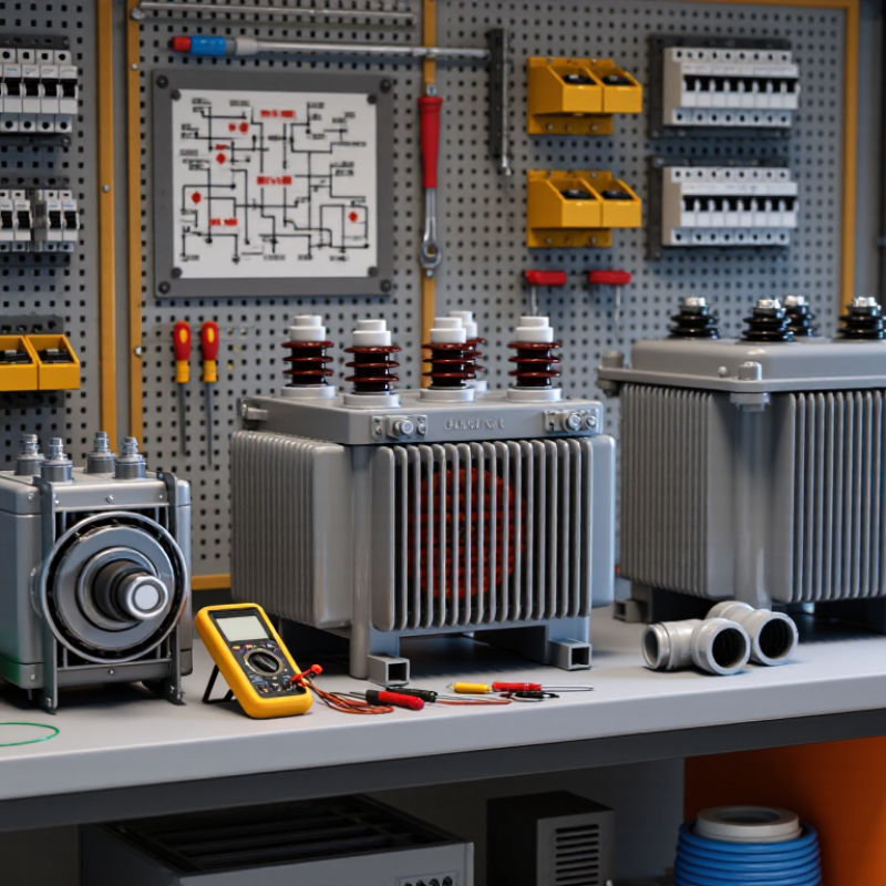
GFCI levels describe how quickly a circuit must detect leakage, not how much power a transformer can deliver. In North American practice, personnel protection commonly uses a 5 mA trip threshold. IEC-based installations often specify 30 mA residual-current protection for additional shock protection. Higher thresholds, such as 100 or 300 mA, usually address equipment or fire risks rather than direct personnel protection.
Transformer selection should begin with the protected load, fault path, and expected leakage current. An isolation transformer can reduce unwanted fault-current paths, but it does not replace a correctly installed GFCI. Choose insulation ratings above the system voltage, adequate VA capacity, and terminals suitable for protective bonding. Check magnetizing inrush too. A transformer that trips during startup is poorly matched, even when its continuous rating looks sufficient. Keep secondary conductors short where possible, and verify grounding with a qualified meter.
The risk is measurable. The Electrical Safety Foundation International reported 126 workplace electrical fatalities and 2,460 nonfatal electrical injuries from 2020 data. That makes leakage control more than a specification exercise. IEC 60364-4-41 and NFPA 70 both emphasize automatic disconnection and effective grounding, but local rules can differ. I would not select a transformer from the GFCI number alone. Site temperature, motor starting current, cable length, and nuisance-trip history can change the decision. This is where judgment remains messy. A commissioning test should record trip time, leakage current, polarity, and transformer temperature under load.
Matching the transformer to the GFCI category starts with the protected load, not the transformer label. For personnel protection, use a properly rated isolation or step-down transformer with a sensitive GFCI device on the secondary side. This arrangement can limit fault energy, but the transformer never replaces GFCI protection. Verify voltage, frequency, load current, and inrush current before selection.
Equipment-protection applications may accept a higher trip threshold, depending on local standards and the installation environment. A ventilated control transformer can suit machinery circuits, while a shielded isolation transformer may reduce electrical noise in sensitive equipment.
For damp areas or portable tools, choose components with suitable enclosure ratings and clear grounding paths. I have seen installations fail because designers matched voltage correctly but ignored transformer leakage current.
Tips: Check the GFCI category, trip sensitivity, and time response together. Confirm compatibility with electronic loads, especially variable-speed drives and switching power supplies. Test the complete circuit after installation, not only the individual devices. If nuisance tripping appears, measure leakage current first. Replacing the GFCI blindly is a weak fix. Standards and required trip levels vary by region, so qualified personnel should verify the final design against current requirements.
How to Select Transformers for Different GFCI Levels in 2026?
Evaluating Voltage, Load, and Grounding Compatibility
Selecting a transformer for GFCI protection begins with voltage compatibility. Match the primary voltage to the available supply. Confirm the secondary voltage suits the connected equipment. Even a small mismatch can cause nuisance trips or unsafe operation. Check frequency, insulation class, and rated short-circuit performance. These details are easy to overlook.
Load calculation must include starting current, not only normal running watts. Motors, pumps, and switching supplies may draw sharp inrush currents. Choose a transformer with enough capacity for continuous load and temporary surges. However, oversizing is not automatically better. A lightly loaded transformer may still create leakage that affects sensitive GFCI settings. Review the GFCI trip threshold and response time with the transformer’s documented leakage current. A qualified electrician should verify these values during commissioning.
Tips: Measure actual operating voltage at the installation point. Inspect cable length, conductor size, and connection torque. Confirm whether the transformer output is bonded, floating, or separately grounded. Grounding compatibility matters. An incorrect bond can create parallel return paths and unwanted trips. Field checks often reveal assumptions that calculations miss. A clean design on paper may behave differently under moisture, motor startup, or damaged insulation. Document test results, and recheck them after major load changes. Local electrical requirements and current technical documentation should guide the final selection.
Practical selection reference for low-voltage transformer systems using common GFCI or RCD residual-current protection levels. Final selection must follow the applicable electrical code, installation environment, protective-device instructions, and a qualified electrical design review.
| GFCI / RCD Protection Level | Typical Protection Objective | Common Voltage Arrangement | Typical Transformer Configuration | Recommended Load Range | Voltage Selection Criteria | Grounding and Bonding Compatibility | Key Selection and Installation Checks |
|---|---|---|---|---|---|---|---|
| 5 mA personnel protection | Protection against electric shock from leakage on personnel-use branch circuits, such as receptacles in wet or high-risk locations. | 120 V single-phase, or 120 V line-to-neutral from a 208Y/120 V or 480Y/277 V system. | Single-phase isolating or control transformer with a 120 V secondary, sized for the connected branch load. | Approximately 0.5–5 kVA for small tools, receptacles, controls, and portable equipment. | Match the secondary voltage and frequency to the load. A 120 V load should not be supplied from a 208 V or 240 V secondary unless the equipment is specifically rated for it. | Bond the secondary grounded conductor and equipment grounding system at the permitted single bonding point. Do not create additional neutral-to-ground bonds downstream of the protection device. | Use a GFCI device that is suitable for transformer-fed circuits. Keep aggregate normal leakage low because nuisance trips can occur when several filters, motors, or electronic loads are connected. |
| 10 mA personnel protection | Enhanced shock protection used in selected applications where a lower residual-current threshold is required by the design or local rules. | Typically 120 V or 230 V single-phase secondary circuits. | Low-leakage isolating transformer with a grounded secondary where required by the installation method. | Approximately 0.5–10 kVA, depending on the connected equipment and inrush current. | Confirm the transformer's no-load and full-load secondary voltage. Excessive voltage drop can cause motor starting problems and electronic equipment faults. | The transformer secondary must have a clearly defined grounding method. A floating secondary may require a suitable insulation-monitoring or protection arrangement rather than a conventional grounded-neutral GFCI configuration. | Choose equipment with low inherent capacitive leakage. Consider time delay, motor starting current, and selective coordination so that the protective device does not trip during normal energization. |
| 30 mA personnel protection | Common residual-current protection level for additional protection against electric shock in many international installations. | 230 V single-phase, 230/400 V three-phase, or 120/208 V three-phase systems, depending on the region. | Single-phase or three-phase isolating transformer with a secondary voltage matching the equipment and supply system. | Approximately 2–100 kVA for lighting, receptacles, small machinery, and distributed equipment. | Verify phase count, line-to-line voltage, line-to-neutral voltage, frequency, and allowable voltage tolerance. Three-phase loads require correct phase sequence and balanced loading where applicable. | Connect all circuit conductors passing through the residual-current sensor, including the neutral when present. The protective conductor must not pass through the sensing core. | Do not use a transformer as a substitute for residual-current protection. Check transformer inrush, harmonic currents, shield capacitance, and downstream surge-protection leakage. |
| 100 mA residual-current protection | Equipment or installation protection where a higher threshold is selected to reduce fire or insulation-fault risk while avoiding nuisance operation. | 208/120 V, 240/120 V, 230/400 V, or other low-voltage secondary systems. | Dry-type distribution transformer or three-phase isolating transformer with a grounded secondary system designed for the distribution load. | Approximately 15–500 kVA, subject to fault-current, thermal, and distribution requirements. | Size the transformer for continuous kVA, motor starting, nonlinear loads, ambient temperature, altitude, and expected voltage drop. A transformer rated only for steady-state load may not handle starting current. | Provide a single system bonding point for a separately derived secondary where required. Coordinate the grounding electrode connection, equipment grounding conductors, and overcurrent protection. | Coordinate the residual-current setting with transformer leakage and downstream protective devices. Confirm that the trip level is high enough for normal leakage but low enough for the intended fault-protection objective. |
| 300 mA residual-current protection | Commonly used for upstream equipment, cable, and fire-risk protection rather than direct personnel protection. | 400/230 V, 480Y/277 V, 600 V-class, or other industrial distribution voltages where permitted. | Medium-capacity three-phase distribution transformer, autotransformer, or isolating transformer, depending on the required isolation and grounding scheme. | Approximately 75–2,500 kVA for plant distribution, large HVAC systems, pumps, and process equipment. | Confirm primary and secondary voltage, short-circuit withstand, impedance, tap range, phase configuration, and available fault current. Transformer impedance affects both voltage regulation and fault-current magnitude. | Grounding must be designed as a complete system, including the transformer enclosure, secondary neutral or reference conductor, grounding electrode conductor, and protective bonding conductors. | Use time-current coordination with feeder and branch protection. High-capacitance cable runs and variable-speed drives may require residual-current devices specifically designed for smooth DC or high-frequency components. |
| GFCI/RCD not installed on the transformer secondary | Not a protection level; this condition is shown as a design warning because transformer isolation does not automatically provide personnel protection. | Any primary or secondary voltage, including 120 V, 208 V, 230 V, 400 V, or 480 V systems. | Any transformer type, including isolating, control, autotransformer, or distribution transformer. | Any load size. | Voltage compatibility alone does not establish shock protection. The device must be evaluated for the actual secondary arrangement and load current. | An ungrounded or incorrectly bonded secondary can prevent a conventional GFCI arrangement from operating as intended. Grounding and bonding must be verified before energization. | Do not assume that galvanic isolation, a low-voltage output, or a transformer enclosure replaces GFCI/RCD protection where the applicable code requires it. |
Design notes: Transformer kVA can be estimated as single-phase kVA = voltage × amperes ÷ 1,000, and three-phase kVA = 1.732 × line-to-line voltage × amperes ÷ 1,000. Select the next suitable rating after considering continuous load, motor inrush, nonlinear-current heating, ambient conditions, voltage drop, and required future capacity. GFCI/RCD trip levels, grounding methods, and acceptable applications vary by jurisdiction and equipment type; verify the 2026 edition of the applicable electrical code and have the installation tested by a qualified person.
Selecting the right transformer begins with the GFCI’s required trip sensitivity. A transformer does not replace GFCI protection. It must support stable operation without creating unwanted leakage paths. Check the transformer’s rated voltage, VA capacity, insulation class, and short-circuit strength. Leave practical headroom, rather than sizing exactly to the calculated load. Small margins can disappear during startup.
Safety starts with the fault path. Isolation transformers may reduce certain risks, but grounding and bonding still require careful design. Confirm how the secondary neutral is treated, and verify that protective devices can detect faults correctly. Shielding between windings can reduce capacitive noise and leakage current. The enclosure should also match moisture, dust, and impact conditions at the installation site. A clean workshop test is not enough.
Reliability needs evidence. Review thermal performance, dielectric test data, temperature rise, and documented production checks. During commissioning, measure primary and secondary voltage under real load. Test GFCI operation after connecting the transformer, not only before it. Watch for nuisance trips during motor starts or switching events. Some field problems remain difficult to predict. That is why accessible terminals, clear labels, and replaceable protection devices matter. Recheck connections after initial heating, because loose hardware can cause gradual failures.
Selecting transformers for different GFCI levels in 2026 begins with the installation standard, not a catalog rating. Determine whether the circuit requires personnel protection, equipment protection, or a specialized threshold for medical or wet locations. Requirements differ by jurisdiction and application. Check the authority having jurisdiction, the latest adopted electrical code, and the equipment instructions. A 30 mA device is not automatically acceptable where a 5 mA personnel level is required. That assumption can fail inspection.
Verify transformer construction against the selected protection level. Confirm isolation, secondary bonding, insulation class, leakage current, interrupting rating, and temperature rise. Match voltage, phase, load inrush, and continuous capacity. Inspectors also examine accessible disconnects, conductor protection, enclosure ratings, and grounding or bonding at the designated point. Keep test records. Before energizing, test insulation and protective-device operation with calibrated instruments. Small details matter.
For 2026 compliance, document the code edition used, local amendments, calculations, certificates, and commissioning results. Recheck requirements after design changes; replacement loads can alter leakage and nuisance-trip behavior. Do not rely on a generic “GFCI compatible” statement. It is too vague. One practical weakness remains: field conditions rarely match drawings perfectly. Moisture, long cable runs, and shared neutrals can change measured current. Photograph terminations, record readings, and obtain qualified review before handover.
No. A properly rated transformer can limit fault energy, but a secondary-side GFCI remains necessary. The transformer is not the protective device.
Match the transformer to the protected load and supply voltage. Confirm secondary voltage, frequency, load current, and inrush current. Use sensitive GFCI protection downstream.
A ventilated control transformer may suit equipment-protection applications. Check the permitted trip threshold and local requirements. Motors can create sharp starting currents.
Choose suitable enclosure protection for moisture, dust, and impact. Provide clear grounding paths. Inspect cable connections carefully after installation.
Transformer leakage current may exceed a sensitive GFCI’s tolerance. Measure leakage before replacing the protective device. Blind replacement is a weak fix.
Include normal demand, starting current, and temporary surges. Motors, pumps, and switching supplies may draw sudden current. Exact sizing leaves little margin.
No. Oversizing is not automatically better. A lightly loaded transformer can still produce leakage affecting sensitive settings. Compare documented leakage with trip sensitivity.
Confirm whether the secondary is bonded, floating, or separately grounded. An incorrect bond can create parallel return paths and unwanted trips. Paper calculations can miss this.
Measure primary and secondary voltage under real load. Test the complete circuit after connecting the transformer. Check GFCI behavior during motor starts and switching events.
Review VA capacity, insulation class, thermal performance, dielectric test data, and short-circuit strength. Use accessible terminals and clear labels. Recheck connections after initial heating.
Choosing the right transformer for each ground-fault circuit interrupter (GFCI) protection level begins with understanding how the protection category affects electrical isolation, leakage-current control, and system response. This guide explains How to select transformers for different GFCI protection levels by comparing transformer types, insulation systems, shielding, and grounding arrangements. It also emphasizes matching the transformer’s primary and secondary voltages, power rating, phase configuration, and expected load to the requirements of the protected circuit.
For safe and reliable operation, transformer selection should include appropriate overcurrent protection, thermal management, fault-response capabilities, and clear grounding and bonding practices. Installers should verify that the transformer and GFCI device work together without nuisance tripping or reduced protection, while confirming enclosure, wiring, testing, and documentation requirements. Finally, the selection process should be reviewed against applicable installation standards and 2026 compliance expectations, with qualified professionals validating the final design before energizing the system.

Smrtr Technology